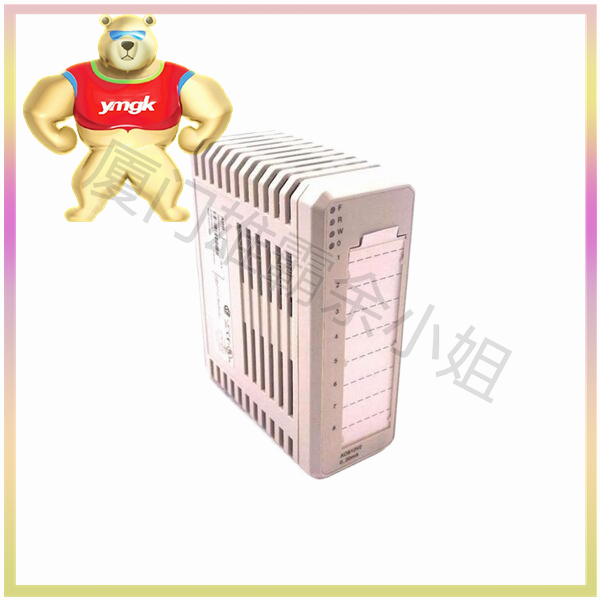
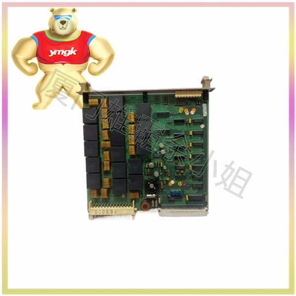
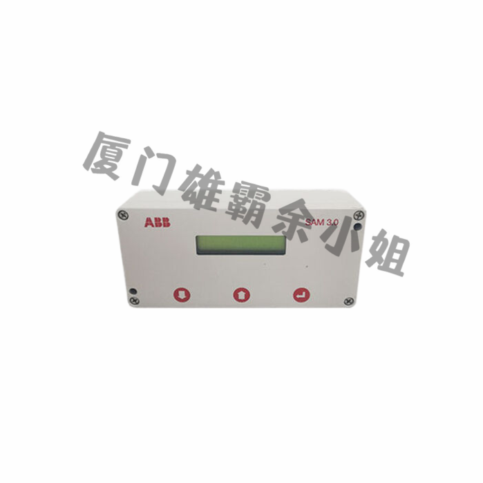
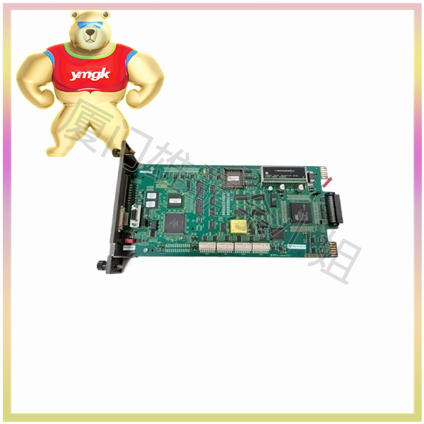
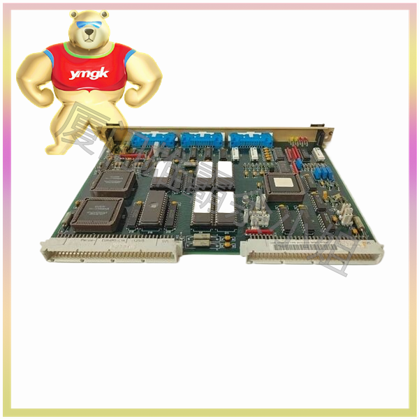
The size of the wires is an important factor in the wiring process of PLC. Input/output terminals of specific wire sizes can accept one or more wires. We need to check if the size and specifications of the wires are appropriate in order to handle the maximum possible current. A programmable logic controller is an industrial computer control system that continuously monitors input devices and makes decisions based on custom programs to control the status of output devices. PLCs typically consist of CPU input and output ports
There are two types of CPUs, one with input/output devices and the other without
PLC operation
In PLC operation, there are four basic steps that occur in a repetitive loop: input scan, output scan, program scan, and internal processing
Input scanning detects the status of input devices connected to the PLC
Output scanning enables all output devices connected to the PLC to be powered on and off
Program scans it to execute user created programs
Internal affairs processing communicates with programming terminals for internal diagnosis
Connect external sensors to PLC
Wire bundling
This is a method used to simplify the connection of each input-output module, as the wires are tied with zip ties, and the tied wires are connected to individual modules, which then pass through the conduit along with other wire bundles with the same signal characteristics. The input and output beams that transmit the same signal will be kept in separate pipelines to avoid interference.
If we need to connect a dual line discrete DC device to a PLC, we need to check whether the device is polarized or non polarized. If it is a polarized device, its wires will be marked, with one wire marked as positive and the other as negative. In this type of connection, the positive wire must be connected to the positive terminal of the PLC input, and the negative wire must be connected to the negative terminal.
In order to connect simple non polarized devices such as buttons and selector switches, the device can be connected through any wire connected to the positive and negative terminals of the PLC.
Special precautions for input-output connections
Some device connections require special attention, including leaky inputs, inductive loads, output fuses, and shielded cables.
Leakage input
Even if some devices are in the off state, there will still be some leakage current, so in order to correct this situation, we need to place a resistor at the input end
Fusion output
To protect the device from moderate overload, if the output does not have an internal fuse, an external fuse must be installed
Protected by
Shielding is to reduce signal coupling. Shielded cables must be used for control lines to protect low-level signals from static electricity and magnetic coupling.

