Main characteristics of PLC control circuit
- Input/output interface:
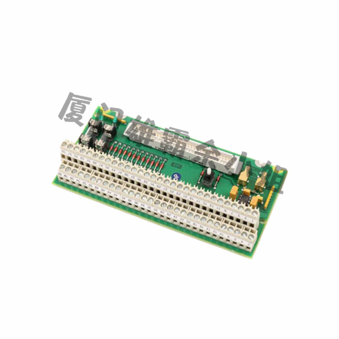
The main feature of PLC control circuits is their highly open input and output interfaces, which can provide interfaces for different types of input and output devices. Common input devices include switches, sensors, and encoders, while common output devices include relays, electric actuators, and so on.
- Control processor:
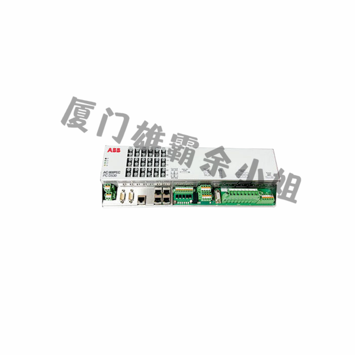
Another major feature of PLC control circuits is their control processor, which is a central processing unit similar to a computer. The control processor is responsible for executing PLC programs and monitoring the status of input/output interface devices. In PLC control circuits, the control processor is the core of the entire system and can be upgraded or replaced as needed.
- programmability:
One of the most prominent features of PLC control circuits is programmability, where programs can be written and adjusted on the control processor as needed. This programmability enables PLC control circuits to adapt to various complex control tasks and application scenarios.
- Embedded:
PLC control circuits are typically embedded systems that can run specific application software programs within them. This makes PLC control circuits very suitable for use in industrial environments, as they can operate normally in noisy, vibrating, and other harsh environments.
- Reaction speed:
The response speed of PLC control circuits is very fast because they can respond instantly to changes in input signals and issue appropriate control signals. This fast response speed is one of the important features of PLC control circuits in controlling and monitoring modern industrial equipment.
In short, the PLC control circuit structure has high programmability, open input and output interfaces, embedded system characteristics, and fast response speed. These characteristics make PLC control circuits widely used in industrial control and automation fields.
The structural composition of PLC control circuit
PLC control circuits typically consist of the following components:
- Central Processing Unit (CPU): The main component responsible for processing input signals, executing programs, and controlling output signals.
- Input/output module: responsible for converting external digital or analog signals into signals that the PLC can recognize, while converting the PLC’s output signals into external digital or analog signals.
- Program memory: stores information such as programs, instructions, and data for CPU execution.
- Working memory: used to store the data required by the CPU to execute programs.
- Communication interface: enables PLC to communicate with other devices (such as human-machine interface, computer, other PLCs, etc.).
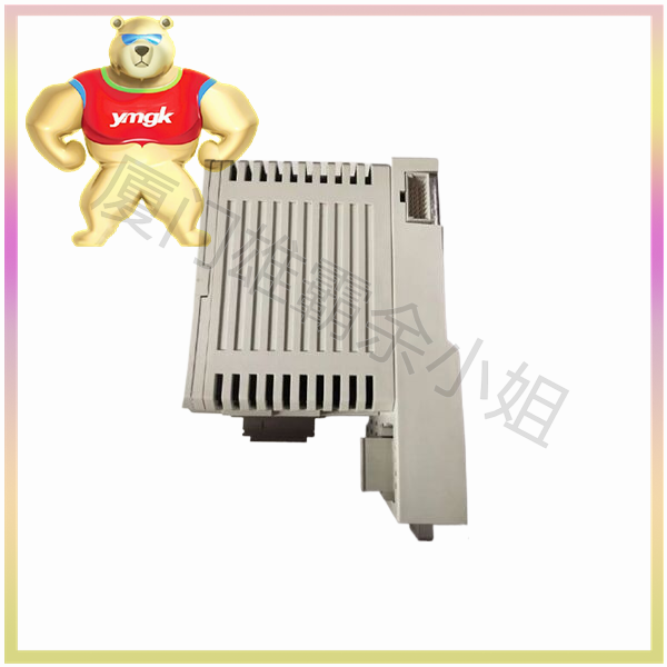
The above components are the most basic parts of PLC circuits, and different brands and types of PLCs may also include dedicated modules such as measurement modules, control output modules, etc. These basic components can be combined according to actual needs to form PLC control circuits suitable for different application scenarios.
Wiring method for PLC control circuit
The wiring method of PLC control circuit is basically divided into the following steps:
Firstly, clarify the equipment to be controlled and its control requirements.
- Design control circuits according to equipment control requirements and select appropriate PLC modules.
- Determine the required input/output modules, as well as necessary power modules, communication modules, etc., based on the specifications of the PLC module.
- Design and arrange input/output signal lines based on the number and position of input/output modules.
- Select appropriate electrical modules based on the electrical configuration in the control circuit, such as relays, button switches, indicator lights, etc.
- According to the electrical configuration design control circuit wiring diagram, connect the input signal to the input module and the output signal to the output module.
- Perform circuit wiring and connect various components, PLC modules, and power supplies according to the wiring diagram.
- Conduct circuit debugging and testing to ensure the reliability and correctness of the control circuit.
- Conduct electrical safety inspections and maintenance, regularly check the tightness of circuit wiring, and keep electrical equipment clean and dry.
Precautions for wiring PLC control circuits
- Connect the signal wires of the PLC input module correctly. The signal line of the PLC input module should be correctly connected to the input signal and should not be connected to the power supply or other unrelated lines.
To reduce noise interference, it is necessary to connect external devices with shielded cables.
- Connect the power cord of the PLC output module correctly. The power cord of the PLC output module should be correctly connected to the corresponding output device and should not be connected to other devices.
- Connect the power cord correctly according to the specifications and maintain the correct polarity connection.
- For high-voltage lines, it is necessary to isolate the PLC input/output module from the controlled equipment through devices such as relays or contactors.
- For devices that may generate high electromagnetic interference, they should be physically isolated or their electromagnetic interference level should be reduced through devices such as filters or chokes.
- Before wiring, confirm whether the PLC configuration is correct and perform corresponding debugging.

