The working principle of PLC controlled motor forward and reverse circuits can be summarized as follows:
Input sampling stage
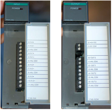
During the input sampling phase, the PLC sequentially reads in all input states and data in a scanning manner, including the states of the forward button, reverse button, and stop button. These input states and data are stored in the input image register of the PLC as the basis for subsequent program execution.
User program execution phase
During the user program execution phase, the PLC executes the program in the order of a ladder diagram or instruction table. When the forward rotation button is detected to be pressed, the PLC will execute the forward rotation control program and output a forward rotation control signal; When the reverse button is detected to be pressed, the PLC will execute the reverse control program and output a reverse control signal; When the stop button is detected to be pressed, the PLC will execute the stop control program and output a stop control signal.
When executing the control program, the PLC will determine the direction of the motor’s rotation through internal logic operations. Specifically, the PLC will determine the corresponding control signal output based on the input forward and reverse button status, as well as the current direction of the motor (forward or reverse). For example, when the motor is currently in a stopped state and the forward rotation button is pressed, the PLC will output a forward rotation control signal to start the motor to rotate forward; When the motor is currently in forward rotation and the reverse button is pressed, the PLC will output a reverse control signal, causing the motor to start reversing.
Output refresh phase
After the user program execution is completed, the PLC enters the output refresh phase. At this stage, the PLC will transmit the status and data in the output image register to the output device (motor drive circuit) through the output circuit, controlling the forward and reverse rotation and stopping of the motor. At the same time, the PLC will also update the status and data of the input image register to reflect the actual state of the current motor.
4、 The key technology of PLC controlled forward and reverse rotation circuit of electric motor
Logic control function: PLC utilizes its internal logic operation function to determine and output corresponding control signals based on the input forward and reverse button states and the current motor rotation state. This is the core technology for implementing forward and reverse control of electric motors.
Interlocking technology: In order to avoid the situation where the forward and reverse control circuits of the motor are simultaneously connected (i.e. short circuit), interlocking function is usually set in the PLC program. When the forward control circuit is connected, the reverse control circuit will be locked; vice versa. This ensures that the motor can only rotate in one direction at any given time.
Delay technology: In order to prevent overloading or damage to the motor during frequent switching between forward and reverse directions, a delay function can be set in the PLC program. When the motor switches from one direction to another, the PLC will first stop the motor for a period of time (usually a few seconds), and then start the motor to rotate in the new direction. This can reduce the load impact and wear of the electric motor.

