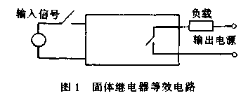
Solid State Relay (SSR) is a new type of contactless electronic switch device developed by combining modern microelectronics technology with power electronics technology. It can achieve contactless connection or disconnection by controlling the current load from 0.1A to several hundred A with a weak control signal (a few milliamps to tens of milliamps). Solid state relay is a four terminal device with two input terminals and two output terminals. The input terminal is connected to the control signal, and the output terminal is connected in series with the load and power supply. SSR is actually a controlled power electronic switch, and its equivalent circuit is shown in the diagram.
The relevant images for this topic are as follows:

Due to its high stability, reliability, contactless nature, and long lifespan, solid state relays are widely used in motor speed regulation, forward and reverse control, dimming, household appliances, oven drying, heating and temperature control, construction and renovation of power transmission and transformation grids, electric drive, printing and dyeing, plastic processing, coal mining, steel, chemical, and military industries.
Working principle of solid-state relay circuit
Solid state relays are different from conventional electromagnetic relays in that they have no contacts, are optically (electrically) isolated between input and output circuits, are assembled from discrete components, semiconductor microelectronic circuit chips, and power electronic devices, and are made of flame-retardant epoxy resin. They are sealed in a casing using encapsulation technology to isolate them from the outside world, and have good pressure resistance, corrosion resistance, moisture resistance, and vibration resistance.
Solid state relays consist of three parts: input circuit, drive circuit, and output circuit.
Here, we will only take the widely used AC zero crossing solid state relay as an example to introduce its working principle. This circuit adopts zero crossing triggering technology and has the characteristics of starting at zero voltage crossing and turning off at zero negative current crossing. A complete sine waveform can be obtained on the load, so the RF interference of the circuit is very small.
The relevant images for this topic are as follows:

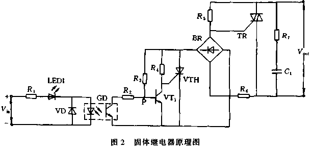
This circuit consists of several parts: signal input circuit, zero voltage detection control circuit, working indicator circuit, bidirectional thyristor control circuit, and absorption circuit. The photoelectric coupler GD is used as an isolation element between the input circuit and the output circuit, and VD is used to prevent the reverse burning of GD caused by the positive and negative connections of Vin.
Circuit operation process: When there is no input signal, the photosensitive transistor in GD is turned off, VT1 is an AC voltage zero point detector, and the base current obtained through R3 saturates and conducts, clamping the gate of VTH at a low potential and in an off state. When there is an input signal, the photosensitive transistor conducts, and the state of VTH is determined by VT1. Therefore, when the power supply voltage is greater than the zero crossing voltage, the voltage at the dividing point P of the voltage divider R3 and R2 is greater than VBE1, and VT1 saturates and conducts. The SCR gate is cut off because it is clamped at a low potential, and the TR gate is in an off state because it does not trigger a pulse. Only when the power supply voltage is less than the zero crossing voltage and the voltage at point P is less than VBE1, G1 is turned off, and the SCR gate is triggered and turned on. When a trigger pulse is obtained at the gate of TR, TR conducts, thereby connecting the load power supply.
When the input signal is turned off, the phototransistor in GD is turned off, and G1 saturates and conducts, causing the SCR gate to clamp at a low potential and turn off. However, at this time, TR still remains conductive, and current still flows through the load until the load current decreases to less than the holding current of the bidirectional thyristor TR with VAC, and then it will automatically turn off, cutting off the load power supply.


