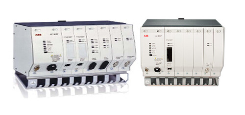
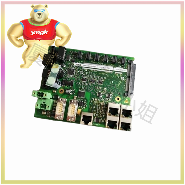
Working principle of switch module
A switch module is an electronic device used to receive and send switch signals. It usually consists of two parts: input module and output module. The input module is used to receive external switch signals, and the output module is used to send switch signals to external devices.
The working principle of the switch module can be divided into the following steps:
1.1 Reception of input signals
The input module receives external switch signals, which can be signals generated by buttons, sensors, etc. The input module converts these signals into electrical signals, which are then processed through internal circuits.
1.2 Signal amplification and shaping
The signal received by the input module may have noise or instability, so it needs to be amplified and shaped. Amplification is to increase the amplitude of the signal, while shaping is to adjust the shape of the signal to a standard switch signal.
1.3 Logical processing of signals
The switch module usually contains logic circuits inside, which can perform logical processing on input signals, such as AND, OR, NOT and other logical operations. These logical operations can be used to implement complex control logic.
1.4 Generation of output signals
After logical processing, the signal will be sent to external devices through the output module. Output modules can be relays, transistors, etc., used to drive external devices.
1.5 Isolation of output signals
In order to protect the switch module and external devices, isolation circuits are usually installed between the output module and external devices. Isolation circuits can be optocouplers, relays, etc., used to isolate electrical signals and prevent current from flowing directly through switch modules and external devices.
Working principle of intermediate relay
Intermediate relay is an electronic device used for receiving and forwarding switch signals. It usually consists of three parts: coil, contact, and iron core.
2.1 Working principle of coil
The coil of the intermediate relay is an electromagnetic coil that generates a magnetic field when it is energized. The magnetic field will attract the iron core, causing it to come into contact with the contacts, thereby changing the state of the contacts.
2.2 Working principle of contacts
The contact is a critical part of the intermediate relay, which is used to receive and forward switch signals. Contact points usually have two states: closed and open. When the coil is energized, the contacts will close, forming a path; When the coil is powered off, the contacts will disconnect, cutting off the path.
2.3 Working principle of iron core
The iron core is another key component of the intermediate relay, used to connect the coil and contacts. Iron cores are usually made of magnetic materials and can be attracted by the magnetic field generated by coils. When the iron core comes into contact with the contact point, the state of the contact point will change.
Method of controlling intermediate relay with switch module
3.1 Direct Control Method
The direct control method is the simplest control method, which directly connects the output signal of the switch module to the coil of the intermediate relay. When the switch module outputs a high level, the coil is powered on and the contacts are closed; When the switch module outputs a low level, the coil loses power and the contacts open.
3.2 Indirect Control Method
Indirect control method is to control the coil of intermediate relay through logic circuit. This method can achieve more complex control logic, such as multi-channel control, conditional control, etc.
3.2.1 Multi channel control
Multi channel control refers to the use of multiple switch modules to control an intermediate relay. This method can achieve the merging and logical processing of multiple signals, thereby realizing more complex control logic.
3.2.2 Condition Control
Conditional control refers to controlling the coil of an intermediate relay based on specific conditions. This method can achieve conditional judgment and logical processing, thereby realizing more flexible control logic.
3.3 Isolation Control Method
The isolation control method is to control the coil of the intermediate relay through an isolation circuit. This method can protect the switch module and intermediate relay, preventing current from flowing directly through them.
3.3.1 Optocoupler isolation
Optocoupler isolation is a common isolation control method that uses optocoupler devices to isolate switch modules and intermediate relays. The input terminal of the optocoupler device receives the output signal of the switch module, and the output terminal drives the coil of the intermediate relay.
3.3.2 Relay isolation
Relay isolation is another isolation control method that uses relays to isolate switch modules and intermediate relays. The coil of the relay is driven by the output signal of the switch module, and the contacts are connected to the coil of the intermediate relay.Working principle of switch module
A switch module is an electronic device used to receive and send switch signals. It usually consists of two parts: input module and output module. The input module is used to receive external switch signals, and the output module is used to send switch signals to external devices.
The working principle of the switch module can be divided into the following steps:
1.1 Reception of input signals
The input module receives external switch signals, which can be signals generated by buttons, sensors, etc. The input module converts these signals into electrical signals, which are then processed through internal circuits.
1.2 Signal amplification and shaping
The signal received by the input module may have noise or instability, so it needs to be amplified and shaped. Amplification is to increase the amplitude of the signal, while shaping is to adjust the shape of the signal to a standard switch signal.
1.3 Logical processing of signals
The switch module usually contains logic circuits inside, which can perform logical processing on input signals, such as AND, OR, NOT and other logical operations. These logical operations can be used to implement complex control logic.
1.4 Generation of output signals
After logical processing, the signal will be sent to external devices through the output module. Output modules can be relays, transistors, etc., used to drive external devices.
1.5 Isolation of output signals
In order to protect the switch module and external devices, isolation circuits are usually installed between the output module and external devices. Isolation circuits can be optocouplers, relays, etc., used to isolate electrical signals and prevent current from flowing directly through switch modules and external devices.
Working principle of intermediate relay
Intermediate relay is an electronic device used for receiving and forwarding switch signals. It usually consists of three parts: coil, contact, and iron core.
2.1 Working principle of coil
The coil of the intermediate relay is an electromagnetic coil that generates a magnetic field when it is energized. The magnetic field will attract the iron core, causing it to come into contact with the contacts, thereby changing the state of the contacts.
2.2 Working principle of contacts
The contact is a critical part of the intermediate relay, which is used to receive and forward switch signals. Contact points usually have two states: closed and open. When the coil is energized, the contacts will close, forming a path; When the coil is powered off, the contacts will disconnect, cutting off the path.
2.3 Working principle of iron core
The iron core is another key component of the intermediate relay, used to connect the coil and contacts. Iron cores are usually made of magnetic materials and can be attracted by the magnetic field generated by coils. When the iron core comes into contact with the contact point, the state of the contact point will change.
Method of controlling intermediate relay with switch module
3.1 Direct Control Method
The direct control method is the simplest control method, which directly connects the output signal of the switch module to the coil of the intermediate relay. When the switch module outputs a high level, the coil is powered on and the contacts are closed; When the switch module outputs a low level, the coil loses power and the contacts open.
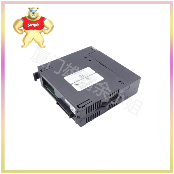
3.2 Indirect Control Method
Indirect control method is to control the coil of intermediate relay through logic circuit. This method can achieve more complex control logic, such as multi-channel control, conditional control, etc.
3.2.1 Multi channel control
Multi channel control refers to the use of multiple switch modules to control an intermediate relay. This method can achieve the merging and logical processing of multiple signals, thereby realizing more complex control logic.
3.2.2 Condition Control
Conditional control refers to controlling the coil of an intermediate relay based on specific conditions. This method can achieve conditional judgment and logical processing, thereby realizing more flexible control logic.
3.3 Isolation Control Method
The isolation control method is to control the coil of the intermediate relay through an isolation circuit. This method can protect the switch module and intermediate relay, preventing current from flowing directly through them.
3.3.1 Optocoupler isolation
Optocoupler isolation is a common isolation control method that uses optocoupler devices to isolate switch modules and intermediate relays. The input terminal of the optocoupler device receives the output signal of the switch module, and the output terminal drives the coil of the intermediate relay.
3.3.2 Relay isolation
Relay isolation is another isolation control method that uses relays to isolate switch modules and intermediate relays. The coil of the relay is driven by the output signal of the switch module, and the contacts are connected to the coil of the intermediate relay.

