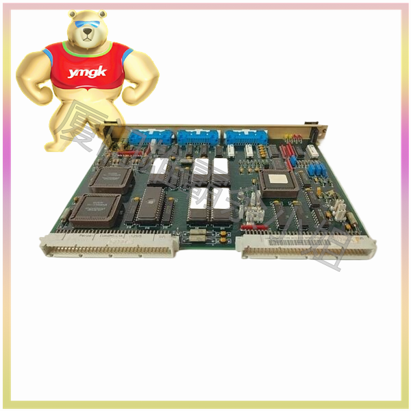
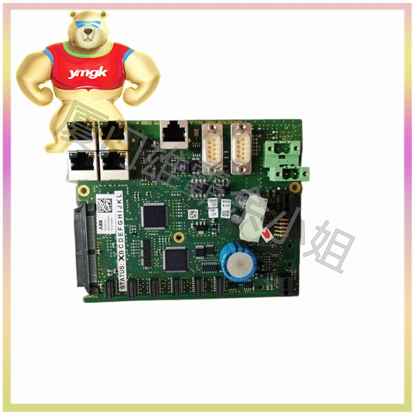
A motion controller is used to generate feedback loops for trajectory points (expected output) and closed positions. Many controllers can also close a speed loop internally. A driver or amplifier is used to convert the control signal (usually speed or torque signal) of a motion controller into a higher power current or voltage signal. More advanced intelligent drives can close their own position and speed loops to achieve more precise control. An actuator such as a hydraulic pump, cylinder, linear actuator, or motor is used to output motion. A feedback sensor such as a photoelectric encoder, rotary transformer, or Hall effect device is used to provide feedback on the position of the actuator to the position controller, in order to achieve closure of the position control loop.
Numerous mechanical components are used to convert the motion form of the actuator into the desired motion form, including gearboxes, shafts, ball screws, toothed belts, couplings, and linear and rotary bearings. Typically, the functions of a motion control system include speed control and point-to-point control. There are many methods to calculate a motion trajectory, usually based on a velocity curve such as a triangular velocity curve, trapezoidal velocity curve, or S-shaped velocity curve. Such as electronic gears (or electronic camshafts). That is to say, the position of the driven shaft mechanically follows the position change of an active shaft. A simple example is that a system consists of two turntables that rotate according to a given relative angular relationship. Electronic cam is more complex than electronic gear, as it makes the following relationship curve between the driving shaft and the driven shaft a function. This curve can be non-linear, but it must be a functional relationship.

