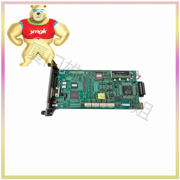
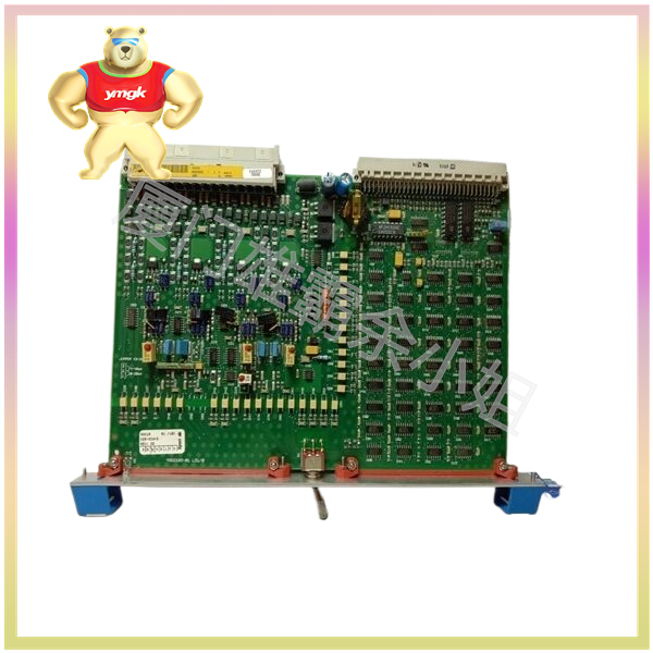
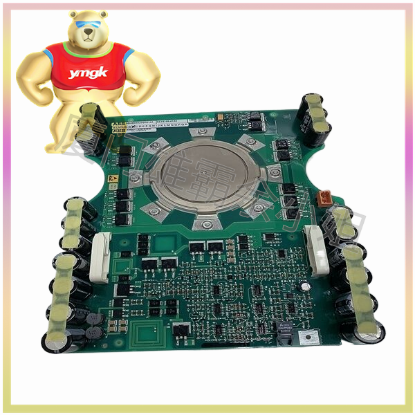
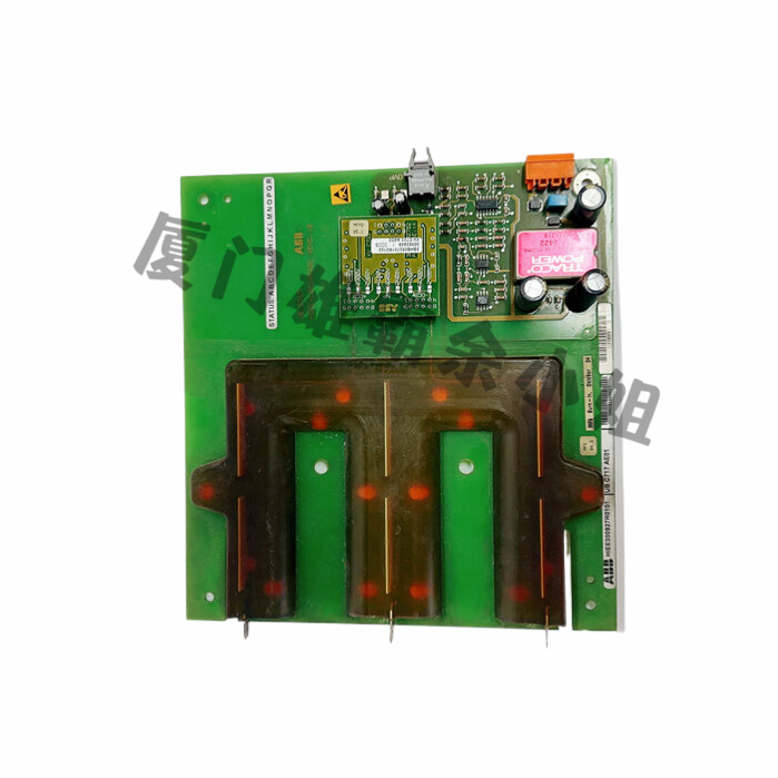
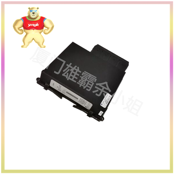
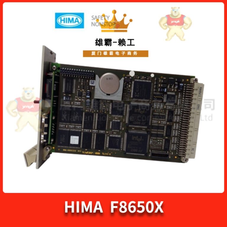
Programmable logic controller is a digital operational electronic system specifically designed for use in industrial environments. It uses a programmable memory to store instructions for performing logical operations, sequential control, timing, counting, and arithmetic operations internally, and controls various types of mechanical equipment or production processes through digital or analog input and output.
The input unit is the input interface connected between the PLC and the controlled equipment, serving as a bridge for signals to enter the PLC. Its function is to receive signals from the main control components and detection components. The input types include DC input, AC input, and AC/DC input.
The output unit is the connecting component between the PLC and the controlled equipment. Its function is to transmit the output signal of the PLC to the controlled equipment, that is, to convert the weak current signal sent by the central processing unit into a level signal and drive the execution components of the controlled equipment.
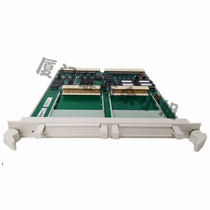
The output types of PLC are generally divided into the following three types:
- Digital output (DO): Digital output is usually a digital signal or binary signal, such as on/off or high/low. It usually controls external devices such as motors, solenoid valves, etc. through relays or semiconductor switches.
- Analog Output (AO): Analog output is typically used to control devices that require continuous control, such as temperature, pressure, flow rate, etc. They typically use current loops or voltage loops to control equipment, such as using 4-20mA or 0-10V signals.
- Pulse output (PO): Pulse output is typically used for counting or measuring position or velocity in applications. They can provide a fixed digital pulse, such as sensor signals, or obtain different pulse numbers through encoders to more accurately control the position and speed of the device.
The difference between PLC input and output lies in their functions and connection methods.
PLC input is the process of inputting signals generated by external devices such as sensors and switches into the PLC for logical control. The most common input devices include digital inputs and analog inputs.
Digital input transmits information in the form of binary signals, typically representing the signal status generated by switch type devices such as switches, buttons, sensors, etc. Digital inputs are often connected through normally closed and normally open contacts.
Analog inputs are used to transmit continuous signals, such as temperature, pressure, flow sensors, etc. They are usually output in the form of 0-10V, 4-20mA, etc., for PLC control.
PLC output is the transmission of control signals from the PLC to the executing equipment to achieve control functions. The most common output devices include digital output and analog output.
Digital outputs typically transmit information in the form of binary signals, such as solenoid valves, relays, lights, and other switch type devices. Digital outputs are usually connected through normally closed and normally open contacts.
The continuity of analog output transmission signals is usually used to control the continuity parameters of executing equipment, such as motor speed, valve opening, etc. Analog outputs are usually connected using PWM, 4-20mA, and other forms.
Overall, there are significant differences in the roles and connection methods of PLC inputs and outputs. Input transmission signals to PLC for its control, while output transmits PLC control signals to executing devices to achieve control functions.

