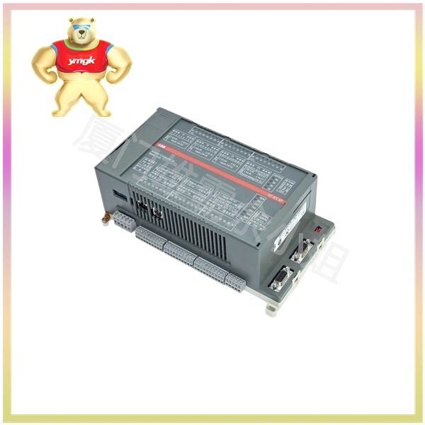
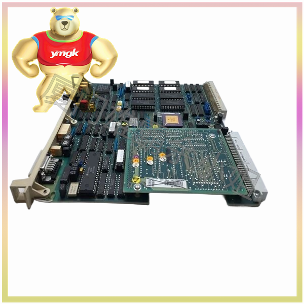
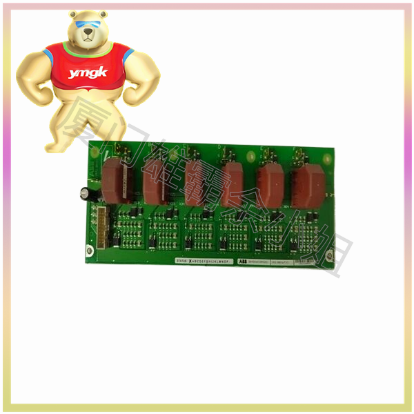
PLC controller mainly refers to a programmable logic controller for digital operation of electronic systems, used to control the production process of machinery. It is also an abbreviation for the names of public limited companies, power line cars, etc. The full English name of PLC is: Programmable Logic Controller, a digital operation electronic system designed specifically for industrial applications. It adopts a type of programmable memory for storing programs internally, executing user oriented instructions such as logical operations, sequential control, timing, counting, and arithmetic operations, and controlling various types of machinery or production processes through digital or analog input/output. It is the core part of industrial control.
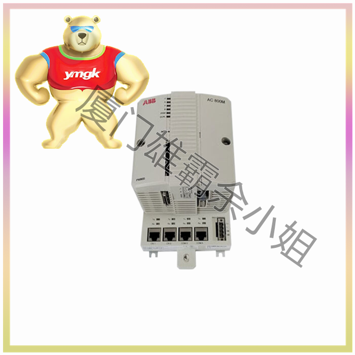
Basic structure of PLC controller
PLC is essentially a computer dedicated to industrial control, with a hardware structure similar to that of a microcomputer, consisting of:
- Power supply
The power supply of PLC plays a very important role in the entire system. Without a good and reliable power system, it cannot function properly, so PLC manufacturers attach great importance to the design and manufacturing of power supplies. Generally, if the AC voltage fluctuates within the range of+10% (+15%), the PLC can be directly connected to the AC power grid without taking any other measures
- The central processing unit (CPU) is the control center of the PLC. It receives and stores user programs and data entered from the programmer according to the functions assigned by the PLC system program; Check the status of power supply, memory, I/O, and alert timer, and be able to diagnose syntax errors in user programs. When the PLC is put into operation, it first receives the status and data of various input devices on site in a scanning manner, and stores them separately in the I/O mapping area. Then, it reads the user program from the user program memory one by one, interprets the commands, and executes logical or arithmetic operations according to the instructions. The results are then sent to the I/O mapping area or data register. After all user programs have been executed, the output states or data in the output registers of the I/O mapping area are finally transferred to the corresponding output devices, and this process is repeated until it stops running.
In order to further improve the reliability of PLCs, in recent years, redundant systems with dual CPUs or voting systems with three CPUs have been adopted for large PLCs. In this way, even if a CPU fails, the entire system can still operate normally.
- Memory: The memory that stores system software is called system program memory; The memory that stores application software is called user program memory.
- Input/output interface circuit
(1) The on-site input interface circuit consists of an optical coupling circuit and an input interface circuit of a microcomputer, serving as an input channel for the interface between PLC and on-site control.
(2) The on-site output interface circuit is integrated with output data registers, gating circuits, and interrupt request circuits, which enable the PLC to output corresponding control signals to the executing components on site through the on-site output interface circuit.
(3) Functional modules: such as counting, positioning, and other functional modules.
(4) Communication modules: such as Ethernet, RS485, Profibus DP communication modules, etc.
PLC controllers are widely used in the field of industrial control. Before the emergence of programmable logic controllers, hundreds or thousands of relays and counters were generally required to form automated systems with the same functionality. However, now, simple programmable logic controller modules that have been programmed have basically replaced these large devices. The system program of a programmable logic controller is usually initialized before leaving the factory, and users can edit the corresponding user program according to their own needs to meet different automation production requirements.

