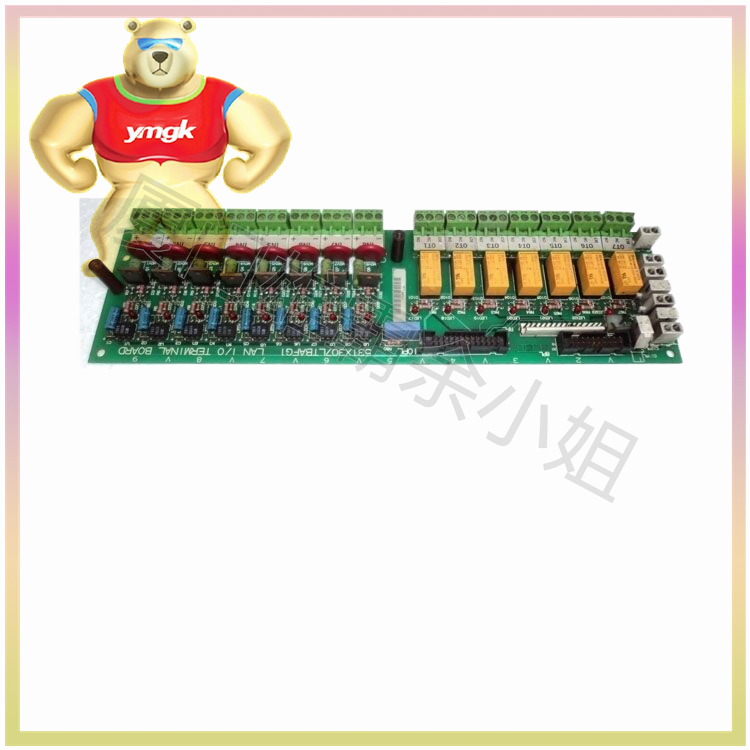
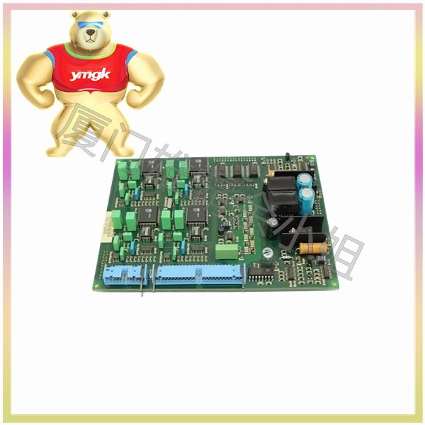
1、 Input device
Input devices are the interfaces between the PLC motion control system and the external world, responsible for converting various physical quantities (such as switch status, analog signals, etc.) into digital signals recognizable by the PLC. In PLC motion control, common input devices include but are not limited to the following:
- Buttons and switches
Button: Button is one of the common input devices in PLC control systems, usually used to start, stop, or switch the operating status of mechanical equipment. Buttons are divided into two types: normally open and normally closed. The normally open button is in the open state when not pressed, and closes when pressed; The normally closed button is the opposite.
Selection switch: The selection switch allows users to choose one from multiple options and is commonly used to set the operating parameters of mechanical equipment or select the working mode.
Limit switch: The limit switch is used to detect the movement position of mechanical equipment. When the mechanical equipment reaches the predetermined position, the limit switch will send a signal to trigger the PLC to execute the corresponding control logic. - Sensors
Sensors are another important input device in PLC motion control systems, which can detect various physical quantities and convert them into measurable signals. In PLC motion control, commonly used sensors include:
Position sensor: used to detect the current position of mechanical equipment, such as photoelectric encoders, magnetic sensors, etc. These sensors can convert the displacement of mechanical equipment into electrical signals for PLC position control.
Speed sensor: used to detect the movement speed of mechanical equipment, such as speed generators, Hall sensors, etc. Speed sensors can provide real-time feedback on the motion status of mechanical equipment, helping PLC achieve speed control.
Force/torque sensor: In some situations where it is necessary to control the output force or torque of mechanical equipment, force/torque sensors can provide necessary feedback signals.
- Other input devices
In addition to the common input devices mentioned above, PLC motion control systems may also include other types of input devices, such as touch screens, keyboards, etc. These devices allow users to interact with PLCs through graphical interfaces or text input, achieving more flexible control methods.
2、 Output device
Output devices are the interfaces between PLC motion control systems and external actuators, responsible for converting the processing results of PLC into signals recognizable by external actuators, thereby driving mechanical equipment to move. In PLC motion control, common output devices include but are not limited to the following:
- Motor driver
Servo driver: A servo driver is a high-performance motor driver that can be used in conjunction with a PLC to achieve high-precision position and speed control. The servo driver drives the servo motor to move according to a predetermined trajectory and speed by receiving control signals from the PLC.
Stepper driver: The stepper driver is used to drive the stepper motor, and controls the rotation angle and speed of the stepper motor by receiving pulse signals from the PLC. Stepper drivers have the advantages of high positioning accuracy and fast response speed, and are widely used in situations where precise control of position and speed is required. - Relays and contactors
Relays and contactors are common output devices in PLC motion control systems, which can switch circuit states based on PLC control signals to control the on/off of external actuators. Relays and contactors have the advantages of simple structure, high reliability, and easy use, and have been widely used in the field of industrial automation. - Electromagnetic valve
Electromagnetic valve is a device that uses electromagnetic force to control fluid on/off, commonly used in PLC motion control systems to control the actuators of hydraulic or pneumatic systems. Electromagnetic valves have the advantages of fast response speed and high control accuracy, which can meet the requirements of complex motion control. - Indicator lights and buzzer
Indicator lights and buzzers are common auxiliary output devices in PLC motion control systems, which can intuitively display the operating status of mechanical equipment or issue alarm signals. Indicator lights are usually used to indicate the operating status of mechanical equipment (such as running, stopping, faults, etc.), while buzzers are used to sound an alarm when abnormal situations occur, reminding operators to pay attention.
3、 Connection and configuration of input/output devices
In PLC motion control systems, the connection and configuration of input and output devices are key steps in achieving precise control. Here are some precautions regarding the connection and configuration of input and output devices:
- Connection of input devices
Correct wiring: The input device should be correctly connected to the input port of the PLC to ensure accurate signal transmission. During the wiring process, attention should be paid to distinguishing between normally open and normally closed buttons, as well as the polarity of sensors.
Signal isolation: In order to avoid the influence of external interference on the input signal of PLC, signal isolation measures can be taken (such as using isolation transformers, optocouplers, etc.) to improve the anti-interference ability of the system. - Connection of output devices
Load matching: The output device should be matched with the output port of the PLC to ensure that parameters such as load current and voltage are within the PLC’s tolerance range. For high-power loads, appropriate protective measures should be taken (such as using relays for isolation, installing fuses, etc.).
Drive capability: When selecting output devices, consideration should be given to whether the output drive capability of the PLC meets the requirements. For situations where high-power actuators need to be driven, PLC output ports with sufficient driving capabilities should be selected or external drivers should be installed. - Programming and Debugging
Programming: In the process of PLC programming, corresponding control programs should be written based on the characteristics and control requirements of input and output devices. The program should be clear, concise, easy to understand, and have necessary annotations and explanations.
Debugging: During the installation and debugging process of the PLC motion control system, input and output devices should be tested one by one to ensure that they can work properly and meet control requirements. At the same time, the entire system should undergo joint debugging and testing to verify its stability and reliability.
4、 Summary
The input and output devices in PLC motion control are key components for achieving precise control. By selecting input and output devices reasonably, connecting and configuring them correctly, and programming and debugging, a stable, reliable, and efficient PLC motion control system can be constructed. In practical applications, appropriate input and output devices should be selected based on specific control requirements and production environments, and operated and maintained in accordance with relevant standards and specifications.

