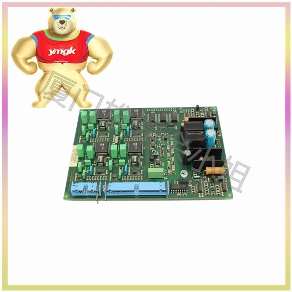
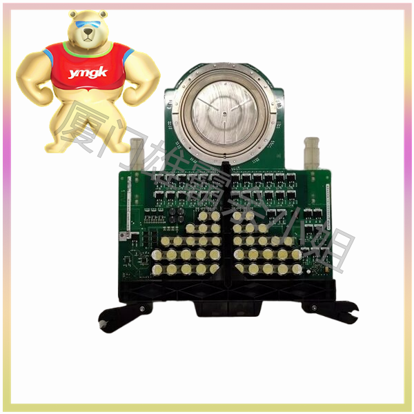
A silicon controlled rectifier (SCR) is a four layer three terminal semiconductor device with unidirectional conductivity, commonly used for power control in AC circuits. The working principle of thyristor is to control the conduction state between the anode (Anode) and cathode (Cathode) by controlling the trigger signal of the gate, thereby achieving control of the output voltage. The following is an introduction to the output voltage controlled by thyristors:
The basic structure and working principle of thyristor
Controllable silicon is a four layer three terminal device composed of alternating stacking of N-type and P-type semiconductor materials. Its structure includes an anode, a cathode, and a gate. The working principle of thyristor is to use the trigger signal of the gate to control the conduction state between the anode and cathode.
When there is no trigger signal from the gate, the thyristor is in a cut-off state, and no current flows between the anode and cathode. When the gate receives a trigger signal, the PN junction inside the thyristor is activated, forming a conductive path between the anode and cathode, and current begins to flow. Once the current reaches above the holding current, even if the gate signal disappears, the thyristor remains conductive until the current drops below the holding current.
The triggering method of thyristor
The triggering methods of thyristors mainly include the following:
(1) Voltage triggering: By applying a certain voltage between the gate and cathode, the PN junction of the gate is turned on, thereby triggering the thyristor.
(2) Current triggering: By flowing a certain current between the gate and cathode, the PN junction of the gate is turned on, thereby triggering the thyristor.
(3) Light triggered: By irradiating a certain intensity of light between the gate and cathode, the PN junction of the gate is turned on, thereby triggering the thyristor.
(4) Temperature trigger: By controlling the ambient temperature, the gate PN junction is turned on, thereby triggering the thyristor.
On and off conditions of thyristor
The conduction condition of a thyristor is that the gate receives a trigger signal and the anode current reaches above the holding current. The shutdown condition of thyristor is that the anode current drops below the holding current.
Control circuit of thyristor
The circuit for controlling the output voltage of a thyristor mainly includes a trigger circuit, a load circuit, and a protection circuit.
(1) Trigger circuit: The function of the trigger circuit is to provide a trigger signal for the thyristor. The triggering circuit can be triggered by voltage, current, light, or temperature.
(2) Load circuit: A load circuit is a circuit connected between the anode and cathode of a thyristor, used to control the output voltage. Load circuits can use components such as resistors, inductors, capacitors, etc.
(3) Protection circuit: The function of the protection circuit is to protect the thyristor from damage in abnormal situations. The protection circuit can adopt overcurrent protection, overvoltage protection, short circuit protection and other methods.
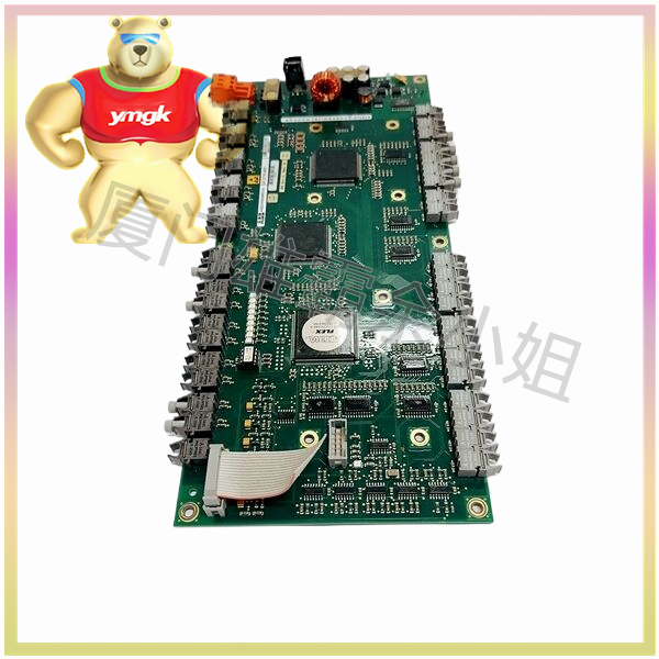
Method of Controlling Output Voltage with Controllable Silicon
There are several methods for controlling the output voltage of thyristors, including the following:
(1) Phase control method: By controlling the triggering time of the thyristor, the phase of the alternating current is changed to achieve control of the output voltage. The phase control method is applicable to AC circuits.
(2) Pulse Width Modulation (PWM) method: By controlling the conduction time of the thyristor, the effective value of the output voltage is changed to achieve control of the output voltage. The PWM method is applicable to DC circuits.
(3) Phase pulse width modulation (PSM) method: By combining phase control and PWM methods, precise control of the output voltage is achieved by controlling the triggering time and conduction time of the thyristor.
Application of thyristor controlled output voltage
Controllable silicon control output voltage is widely used in industrial, civilian, and military fields, such as motor speed regulation, lighting regulation, electric heating control, power management, etc.
Advantages and disadvantages of thyristor controlled output voltage
(1) Advantages: Controllable silicon has the advantages of simple structure, low cost, convenient control, and high reliability.
(2) Disadvantages: The triggering current of thyristors is relatively high, which requires high requirements for the triggering circuit; The conduction loss of thyristors is significant, which affects the efficiency of the system.
The development trend of thyristor controlled output voltage
With the continuous development of power electronics technology, the technology of thyristor controlled output voltage is also constantly innovating and improving. The future development trends mainly include:
(1) Improve the triggering sensitivity of thyristors and reduce the triggering current.
(2) Optimize the structural design of thyristors to reduce conduction losses.
(3) Develop new triggering methods, such as voltage current composite triggering, temperature light composite triggering, etc.
(4) Combining modern control theory to achieve intelligent control of thyristors.
(5) Develop new power devices such as IGBT, MOSFET, etc. to replace some applications of thyristors.
In summary, thyristor controlled output voltage technology has broad application prospects in the field of power electronics. Through continuous optimization and innovation, thyristor technology will provide more efficient, reliable, and intelligent solutions for power electronic systems.

