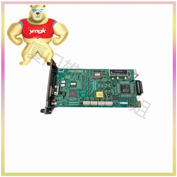
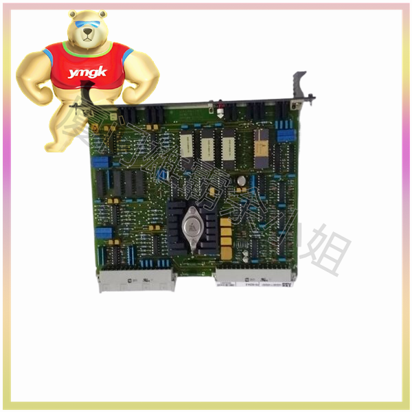
It is usually not wrong to connect analog and switch signals separately on different modules, and the wiring methods are also different. Here, we will briefly describe the difference between switch signals and analog signals, using Mitsubishi small PLCs to illustrate. The switch quantity is composed of input and output ports, located on the basic unit of the PLC. The top is the input terminal block, and the bottom is the output terminal block. The input X is driven by a DC 24V power supply, and the output is determined by the relay output and transistor type of the PLC, where the output contacts of the transistor can only pass through DC power.
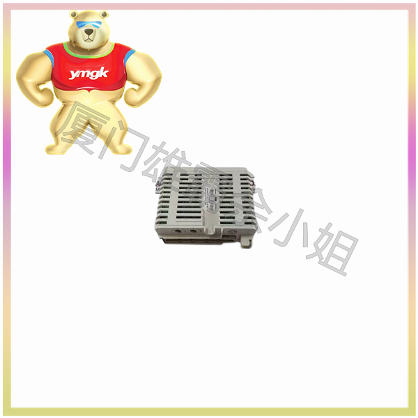
And the analog quantity is not on the basic unit of the PLC, for example, it can be completed through expansion modules, adding modules on the left or right side of the basic unit. For AD modules, the positive pole of the signal is connected to VIN or AIN, and the negative pole is connected to COM terminal. For DA modules, the positive pole of the output signal is connected to VOUT or IOUT, and the negative pole is connected to COM.
Based on the above analysis, the signal types used for analog and switch signals are different, and there are significant differences in the wiring positions and methods used on PLCs. Generally, there is a very small chance of misconnection. According to your question, if the analog input enters the switch, it is very likely to damage the module if it is AC power. If it is DC power, such as button input 24V, the ERR indicator light on the PLC may light up. After troubleshooting, it will display “channel upper limit range overflow”, and the input analog value exceeds the specification range.

