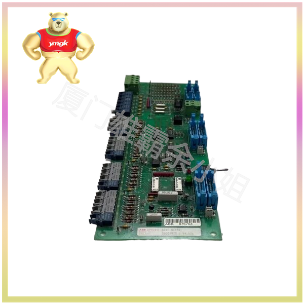
In industrial automation control, we often encounter various concepts such as switch quantity, digital quantity, analog quantity, pulse quantity, etc., and the digital quantity acquisition module is used to acquire digital quantity. In general, the digital quantity we refer to is a signal type composed of 0 and 1, which is usually an encoded and regular signal. However, for switch quantities, contact closure can be considered as 1 and contact disconnection as 0. For example, the DAM-5161 switch quantity input module of Shenzhen Chengkong Electronics converts switch quantities into digital quantity acquisition signals. Analog quantities can be quantified by setting critical values, with values less than the critical value being 0 and values greater than or equal to the critical value being 1.
So at first glance, you can tell the obvious differences that exist. For example, the switch quantity is an on/off signal or a passive signal, and the resistance testing method is a resistance of 0 or infinity, mainly referring to the input and output quantities, which are the auxiliary contacts carried by a device. For example, the auxiliary contacts of the relay device carried by the temperature controller of a motor are the motor’s over temperature displacement, the auxiliary contacts of the valve cam switch are the valve switch displacement, the auxiliary contacts of the contactor are the contactor’s displacement after the contactor’s action, and the auxiliary contacts of the thermal relay are the thermal relay’s displacement after the thermal relay’s action.
These points are usually transmitted to the PLC, and the power is usually provided by the PLC or integrated protection device. They do not have their own power supply, so they are called passive switch contacts, also known as PLC switch contacts. Analog quantity refers to some continuously changing physical quantities, such as voltage, current, pressure, speed, flow rate and other signal quantities. Analog signal is a signal with amplitude continuously changing over time, usually with voltage signal ranging from 0-10V and current signal ranging from 4-20mA. It can be collected using the analog module of PLC, and after sampling and quantization, it can be converted into digital quantity.
But do you know why analog signals are converted into 4-20mA current signals instead of 0-20mA current signals or 0-10V voltage signals? This is because the voltage signal of 0-10V is easily affected by external electromagnetic interference, especially when the cable length is long. If a current signal of 0-20mA is used, it is impossible to determine whether the fault 0mA is caused by cable breakage or the normal 0mA output due to the pressure itself being 0kpa when the current signal is 0mA.
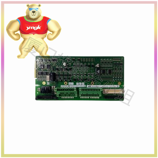
As for pulse, it is the signal quantity of the instantaneous voltage or current changing from one value to another. After quantization, its continuous and regular change is called a digital quantity. If it changes from 0 to a fixed value and remains unchanged, it is called a switch quantity. In fact, many people confuse digital quantities with switch quantities and analog quantities. It is relatively easy to distinguish them because digital quantities are defined as discrete signals that vary intermittently in time and value, and the signal they represent is a digital signal. And the digital quantity is a signal composed of 0 and 1, which is encoded to form a regular signal, and the quantized analog quantity is the digital quantity. Analog quantity is defined as a signal that continuously changes in both time and value. Switching quantity reflects the state signal such as switch on/off, while analog quantity reflects the measured value of electricity such as current and voltage. So, through these pieces of information, we can clearly understand the differences between these several.

